 A few months back I built a full LoRaWAN gateway node for The Things network, and now I’m finally getting around to writing it up. I’d recommend this project to anyone interested in IOT, as it’s very edudational, and you’ll be helping expand the LoRaWAN network coverage in your area. In this build, I use a Raspberry Pi, a RAK831 8-channel gateway and an adapter board (also from RAK) that allows the RAK board to be mounted easily on the Pi.
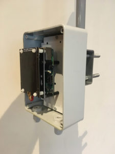
Here’s what we’re aiming at, the Pi mounted in a waterproof enclosure, which will be mounted on a pole high up on my chimney. There’s other cables and components to go into the box in this picture, but you get the idea. 🙂
I don’t go into the detail of setting up the Raspberry Pi with the RAK831, etc, there’s plenty of info already out there on the net covering that, so this blog article focuses more on the physical build.
I’ve done a YouTube video of the build, which has additional information, so it’s worth watching as well if you’re building your own gateway.
[embedyt] https://www.youtube.com/watch?v=gC-quM61Ft4[/embedyt]
List of Components
- Raspberry Pi 2 Model B
- RAK831 LoRaWan Gateway
- Adapter Board (available as a kit from AliExpress
- Adjustbale 2A Buck DC-DC converter (search adjustable buck on aliexpress.com)
- POE Injector x 2 (Aliexpress)
- DHT22 Temp/Humidity sensor (AliExpress)
- Outdoor Cat5e cable plus RJ45 connectors (sourced locally)
- 868MHz Omni Antenna, 10dBi (AliExpress)
- N-Connector Male to SMA pigtail (connects RAK831 to antenna)
- Home made, you should be able to source on eBay or Aliexpress.
- IP56 box, cable glands, and mounting bracket from local hardware store.
- Misc nylon standoffs, nuts and bolts (eBay)
- Waterproofing for Antenna (Insulating tape plus mastic tape, sourced locally, “Denso tape” should do just fine) OR (AliExpress)
The Build
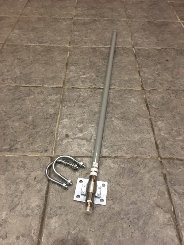
Here’s the antenna. It’s a 10dBi 868MHz antenna, which is the frequency we’re allowed to use in Ireland. The antenna came with the brackets show, but as we’ll see later, I only used a small portion of the bracket.
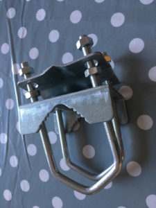
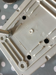
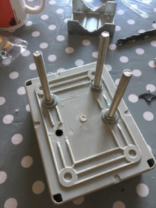
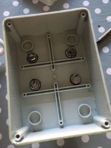
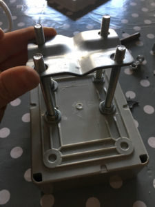
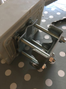
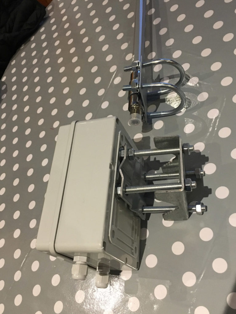
The set of six images below shows the mounting bracket being attached to the box. A local hardware store had an ideal bracket, normally used for TV antenna or Satellite dishes. The waterproofing was achieved by putting some insulating putty around the washers before tightening (click images to enlarge).
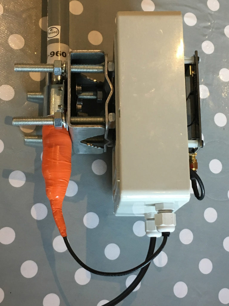
The next step was to see how I was going to mount the antenna and the enclosure on the pole. Since it’s a rather awkward and dangerous position up on my chimney, I wanted to minimise the amount of work I had to do. When I placed them together on the table, I noticed I could half the amount of work if I mounted the antenna on the back plate of the enclosure bracket.
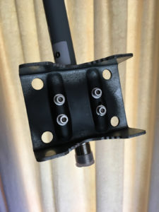
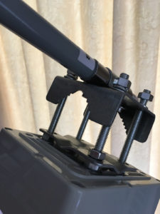
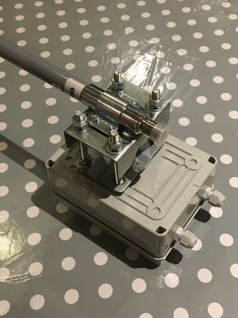
So I drilled 4 holes in the bracket, and bolted the antenna to it. I used a tap and die kit to create threads in the bracket, so I could use the existing antenna plate and bolts. After drilling, I painted the holes, as the bracket was galvanised, and I wanted to minimise the rust due to me drilling holes. Not ideal, but it’ll do.
And here’s the antenna mounted to the bracket. Now I only have to tighten 4 bolts onto the pole while I’m up on the chimney instead of 8, great!
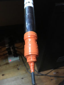
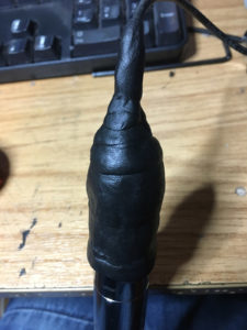
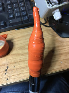
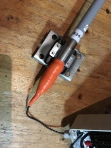
Next is to waterproof the pigtail when it’s attached to the antenna. This is by far the most common point of failure in WiFi systems I’ve set up in the past, so pay special attention to this part. My usual method is to use a layer of insulating tape, then a layer of insulating putty overlapping the first layer of tape, then a final layer of insulating tape to overlap tat again. The stages are shown in the following four images. “3M Scotchfil Electrical Insulation Putty” is quite a good one. By the way, the pigtail you use will need to match the SMA connector on the RAG gateway and the connector on the Antenna. IN this case, the antenna is an N-female connector, so the pigtail had to be N-Male on one end, and RP-SMA on the other end. I can’t quite remember whether it was male or female, but you should be able to tell by turning the gateway over and looking at it’s connectors. 😉
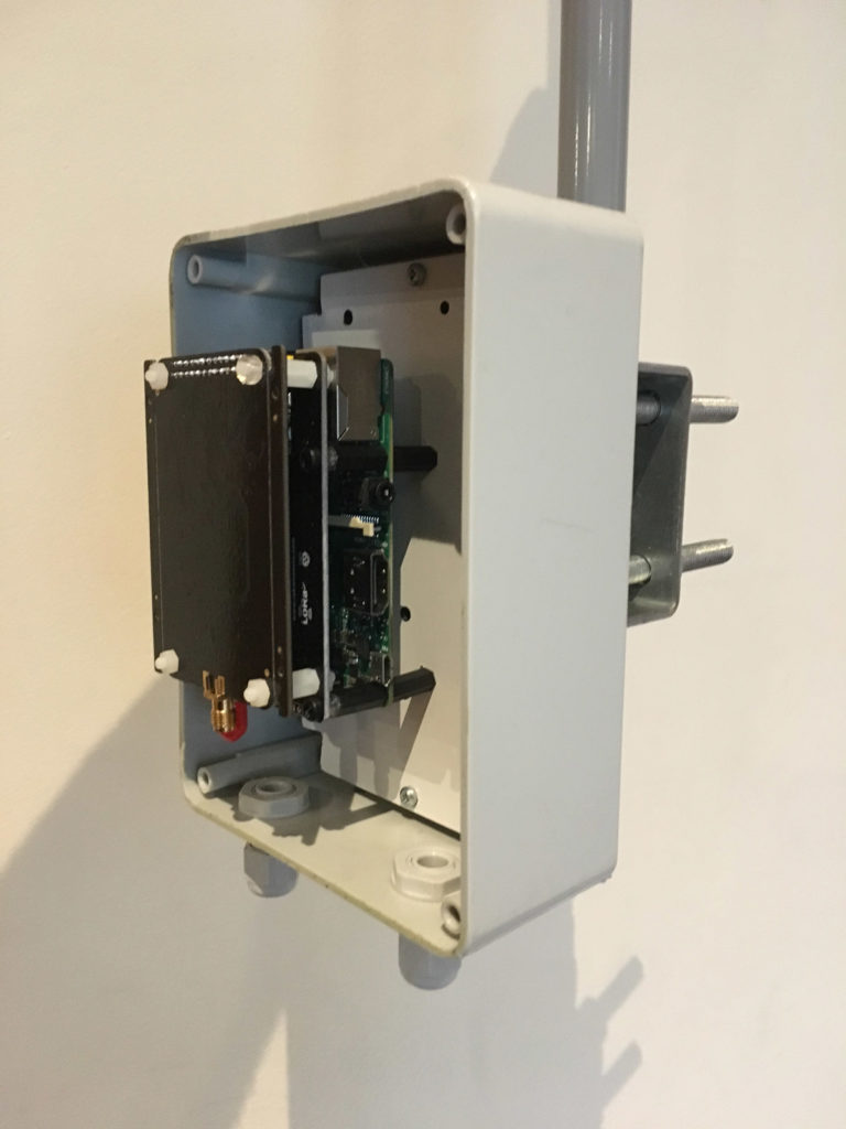
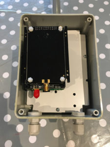
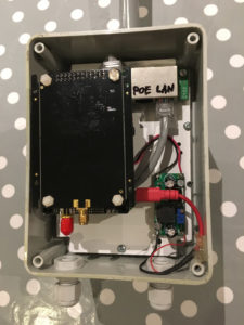
The next step was mounting the Raspberry Pi and RAK830 LoRaWAN Gateway board inside the enclosure. I hacked a piece of dibond to fit, but thin plywood or plastic should do fine. The holes were drilled by hand on an as-needed basis 🙂
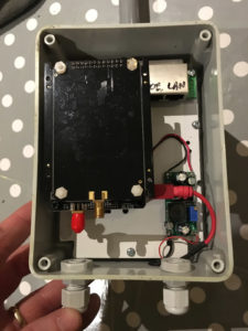
And as I added more components, I kept drilling, adding more standoffs, etc. until I had everything I needed mounted to the dibond sheet. We don’t want any components rattling around in the box when the pole is waving back and over in that Irish weather.
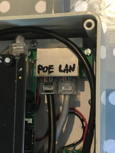
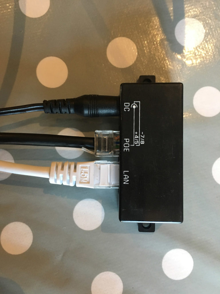
I had a POE adapter which I tool the case off to save a bit of space, so I can take a standard long Ethernet up to the enclosure with 12V on the relevant pins, then tap off the 12V to the DC-DC converter giving me 5V for the Pi and Rak Gateway. There’s a similar POE adapter inside the house feeding the 12V up the cable.
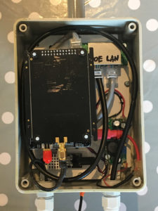
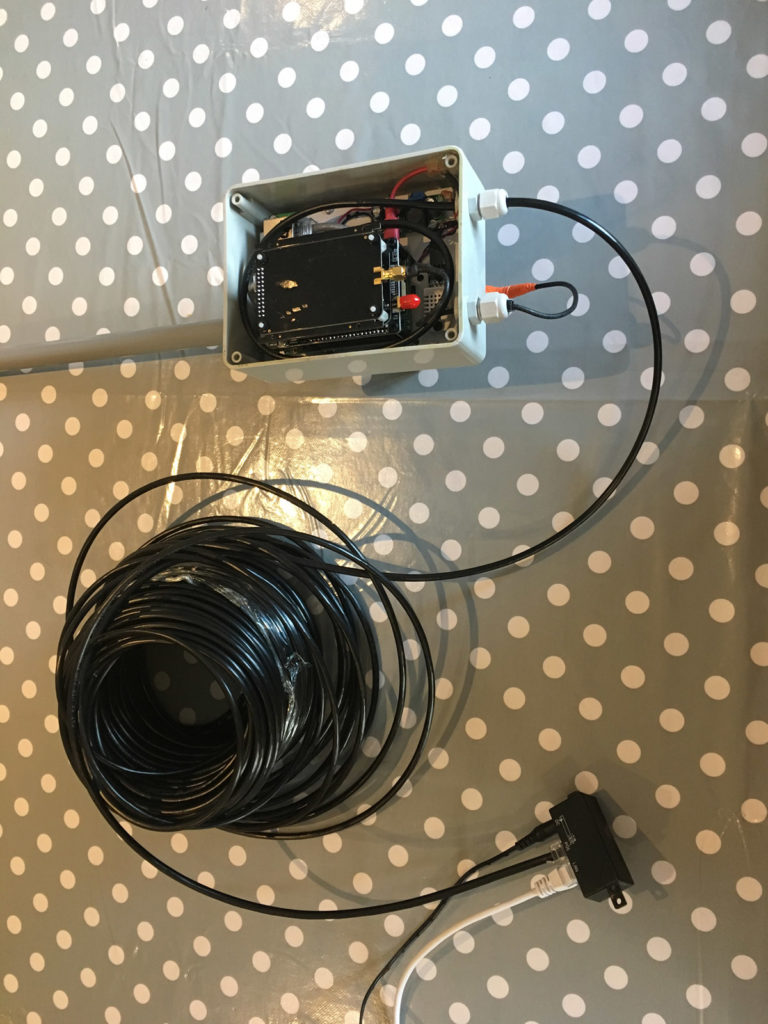
Here’s the enclosure with all the Ethernet cables.
And here’s the other end of the setup, this will sit inside my house.
And the full setup with long Ethernet cable. So you can see (from bottom to top), router to white cable to POE injector, which is also being fed 12V from a standard wall-wart PSU (I think it’s rated at 3A). Then we have the long cable going from the POE injector going all the way up to the enclosure into the other POE injector (what’s the opposite of injector? They are both exactly the same on each end, anyway, FYI). The power is taken from that to a 2A DC-DC converter, giving out 5V for the Pi and Gateway. There’s also a very short Ethernet cable going from the POE unit to the Pi. So it’s wired directly into my house Ethernet rather than WiFi, for reliability reasons.
So after some testing, we’re now we’re ready to put the front cover on, tighten it up, and get out the ladder. (It’s important to test everything, make sure everything is working, including the LoRaWAN gateway, as there may be subtle power issues that you may not notice till it’s all up on the pole. So test extensively before mounting. Unless you’re installation is easy to get to, of course! 🙂
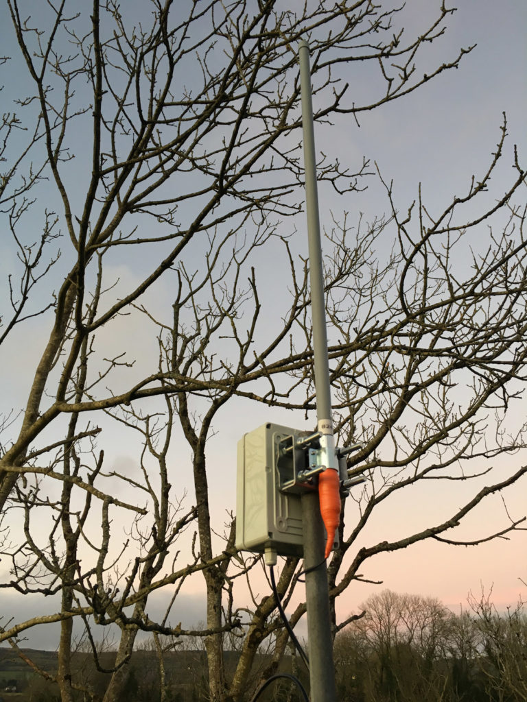
So here’s the gateway installed. I was standing on top of the chimney breast about 25 feet from the ground (I should have taken a selfie).
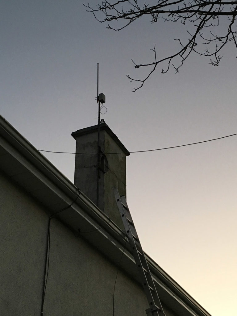
And finally a shot of the whole setup from the ground.
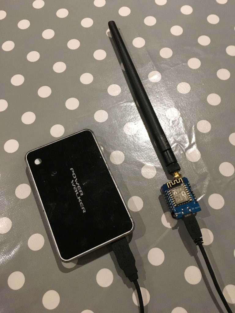
So, once I got back down I confirmed that it all powered up OK, and that I was able to receive traffic from my test sensor node, shown here:
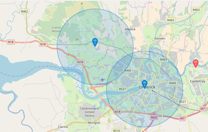
This node is what I use to transmit LoRa packets for testing to see how far I can see my node. I’ve only got about 10K out of it, as my house is in a low-lying area.
Anyway, I hope you find this useful. I’m on TheThingsNetwork as climberhunt, part of the Limerick community. Feel free to drop me a message! 😉
Well done – nice job