 Over the past few months, I’ve been building a DIY Intruder Alarm, so here’s a brief overview of it’s layout and functionality. It’s based on a Raspberry Pi, but there’s nothing to say that it couldn’t be based on any single board computer with an adequate number of GPIO inputs, Up-board, Minnowboard, Beaglebone, etc.
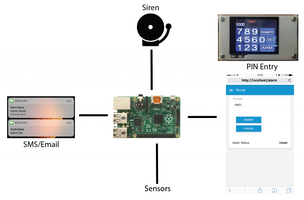
So here’s a very simple overview of the system.
At the core is the single board computer. This takes inputs from a variety of sensors, reed switches on doors and windows, vibration sensors, switches, etc. There’s different algorithms for each input. For example, the door we use to enter an exit the building has a delay on it so that we can set and unset the system, and all the other doors will immediately trigger the alarm when opened. Some switches are anti tamper, so that if they are triggered they will immediately activate the alarm and send and SMS even if the system is not armed. This is useful to prevent tampering with various parts of the system to prevent activation later on when the system is armed. Others are also immediate regardless on whether the system is set or unset, such as smoke and gas detectors.
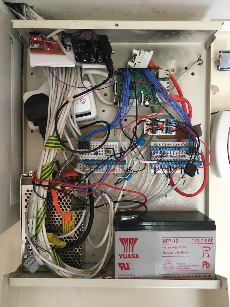
I’m not an expert in alarm system, so I’m sure there are ways to get around this, but I sure had fun building it! Have a look at the internals of the panel:
I agree it’s quite messy, I’ll get around to tidying it up someday. 🙂
There’s a power supply with UPS capability that charges a battery so that the system still works when the main electricity supply is unavailable. That applies to other critical parts of my home network, including the WiFi network, the LTE connectivity, etc. The white cables coming in are from the sensors/switches, and I can also send out power to any sensor that required power such as the motion sensors.
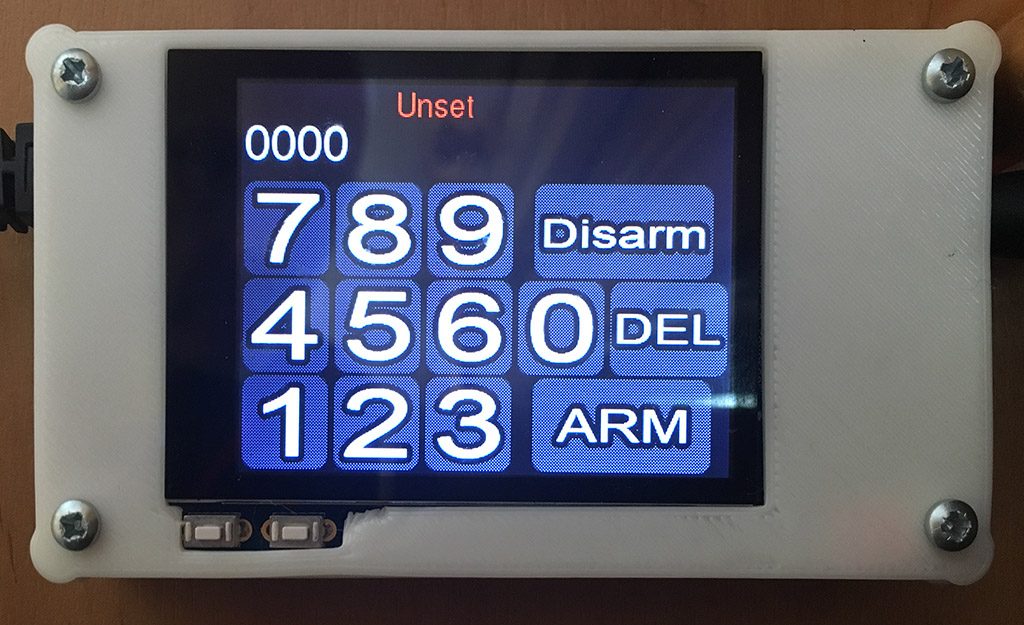
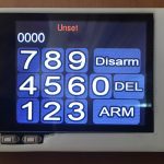
The system can be armed/disarmed in a couple of ways. There’s a panel with a touchscreen mounted elsewhere on the premises that allows a pin code entry:
It’s a Raspberry Pi with a 2.8″ touchscreen interface with a modified version of the PiPhone software I developed in a previous project build. The backlight on the screen can be turned on/off using one of the buttons below the screen. The case is a 3D printed custom design. I’m sure there are easier ways to do this. There are lots of types of numeric keypads available on eBay for example. I happened to have the hardware lying around, so made use of it. Why buy more stuff when you can re-use what you have! 🙂
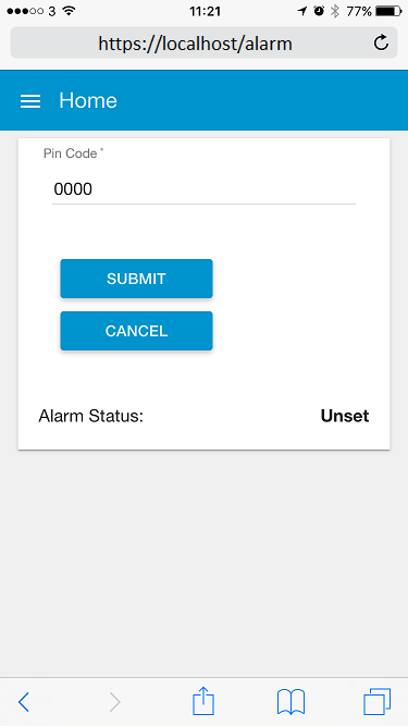
An alternative way is via web interface driven by the node-red back-end that I can use from anywhere on my smartphone (once I’m tunnelled into my private network):
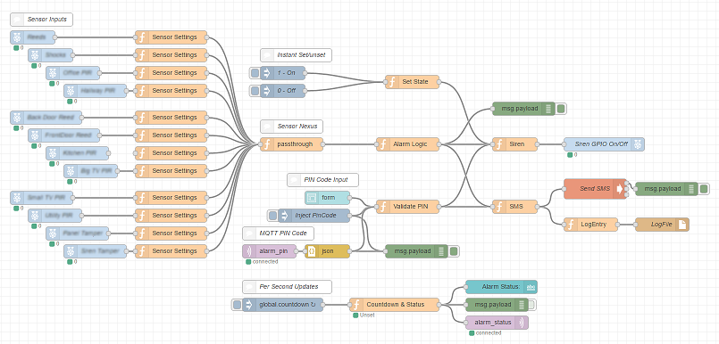
Speaking of the node-red back-end, here’s an image of the nodes and their connections:
So the node-red back-end is connecting everything together. The sensor inputs on the left feeding into the alarm logic where it decides what action to take depending on the status of the system, and which input is active. Then it decides whether to trigger the sirens and send an SMS/email/other notification to the list of notification targets (people/cloud services/logfile, etc.)
The number of sensor inputs hides the number of sensors, as one input handles all the reed sensors on the loop, and there could be any number of those. Also, each zone of vibration sensors comes back to one input. So for the 12 inputs shown the node diagram above, there could be dozens and dozens of actual physical sensors. Also, I was lucky enough to have the premises pre-wired during construction with 6-core cable everywhere, making it very easy to add in sensors. There are many wireless solutions available on the market for situations that don’t have pre-existing wiring available.
On part of the Security solution I’ve built is my DIY cameras, which are typically self builds with Raspberry Pi Zero W with the miniature Pi Camera module. The PiKrellCam software I use with them gives excellent motion detection with very little CPU overhead. Some of the cameras are Infra Red versions for night vision. I’ll hopefully cover these in more detail in a future blog article.
